2006 Mazda 3 2.3L Alternator
The 2006 Mazda 3 is a "smart alternator" system where the PCM is used to regulate charging. The output voltage level varies based on the temperature of the battery from the battery sensor and depends on the charging strategy employed by the PCM. The PCM will vary the voltage for the following reasons:
- To improve the life of the battery by decreasing the charging voltage when the battery is warmer.
- To improve the performance of the vehicle by reducing parasitic drag from the alternator under wide-open-throttle (WOT) conditions.
- To reduce the load on the starter when starting the engine.
- To reduce idle sag when electrical loads are increased at idle.
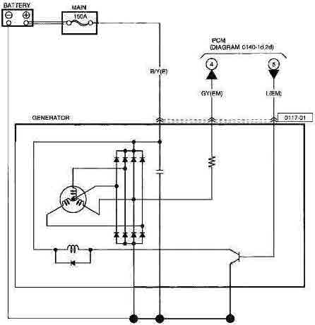
The Mazda 3 alternator uses a
wye-connected stator generating three phases of AC from a rotating field coil.
The field coil is energized by a transistor on the alternator that sources power (transistor collector) from the output of the alternator, and sinks current through the emitter to ground.
The output of the alternator is directly connected to the battery through a 150 amp fuse, while the chassis of the alternator serves as the ground. DC output is provided by rectifier diodes
integral to the alternator chassis. Control over the alternator's output is provided by regulation of the field coil transistor. The base of the field coil transistor is connected to pin
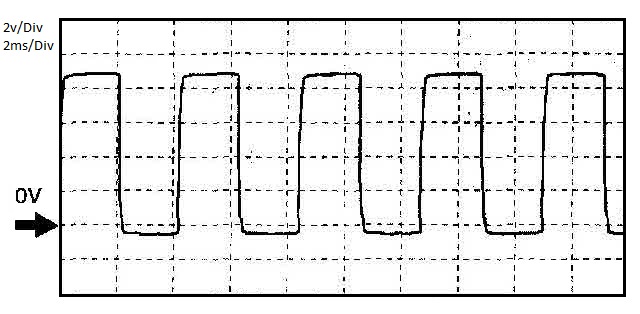
2AQ of the powertrain control module (PCM). The PCM pulse width modulates (PWM) pin 2AQ (vs. pin 2AA ground) using 250 Hz (4 ms) pulses to pin L on the alternator connector. There is a capacitor
between power and ground to reduce AC ripple in the output.
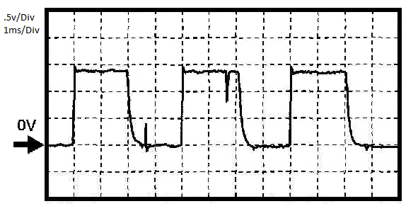
The GY connection at the alternator connects to pin 2AM on the PCM and is a phase pickup from one leg of the three stator windings in the generator. This 250 Hz (4 ms) PWM signal
is used to determine the electrical load on the alternator. If the PCM senses greater than 20 amps from the alternator and senses the bus voltage to be below 8.5V while the engine is
runing,
DTC 2503 will be set.
2006 Mazda 3 2.3L Alternator Schematic

2006 Mazda 3 2.3L PCM Output on pin 2AQ
The L pin on the alternator should still permit the alternator to be tested by removing the alternator wiring with the exception of the output to the battery and then connecting a 12v +
lead through a test light (filament, not LED) to pin L. The voltage at the battery should rise to the maximum value.
2006 Mazda 3 2.3L Alternator Output on pin 2AM

The chart above was taken at 650 rpm idle conditions.
Problem
Since I have opted to retain the Ford Fusion accessory drive layout, the 2006 Mazda 3 Alternator no longer has a mount compatible with the exhaust side of the engine block.
Solutions
After some study at the junk yard and online, it turns out that the mazdaspeed 3, the later Mazda 3, and the 2006-2007 Mazda 6 use the same accessory drive layout as the Ford Fusion. They also all seem to have compatible alternators, although each is somewhat different in how the alternator is cooled and the clocking of the wiring connections relative to the mounts. The alternator connector in the wiring harness will not mate with any of the replacement alternators. I suspect that all of the Mazda alternators with the correct mounts will work, and appear to use the same three-pin connector (of which, only two pins are used). I used a new 2007 MazdaSpeed 3 alternator with the Ford Fusion alternator heat shield, and the connector from a 2006 Mazda 6. Had I not bought the alternator before going to the junk yard, I would have simply used the 2006 Mazda 6 alternator and connector and heat shield.
I originally tried to use the 2010 Ford Fusion alternator that came with my donor engine. The interesting thing about the Ford Fusion on-alternator regulator is that in the absence of a
commanded voltage level setting from the PCM, the alternator will self-excite the field coil and start charging at 13.5v if the engine RPM reaches 2,000 rpm (4,500 rpm at alternator) for more than 3 seconds. This makes the Fusion alternator behave nearly as a one-wire alternator if the A lead is connected to alternator output and the other two wires are kept disconnected. I discovered this after
reading the pinpoints test for "alternator not charging" in the Ford Fusion repair manual. Unfortunately, the PWM used for the Fusion is different than the Mazda scheme in PWM frequency and possibly in other ways. It would be difficult to make an interface between the Mazda PCM and the Ford alternator without additional documentation. The car will run indefinitely charging at 13.5v, but the battery will be damaged over time due to not receiving a full charge. Also, the headlights will be dim.
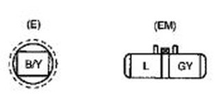
Alternator Connections
The 2006 Mazda 6 had a connector with a green wire and a red/yellow wire. The green wire should be connected to the blue wire coming from the Mazda 3 PCM. The red/yellow wire on the 2006 Mazda 6 alternator should connect to the gray wire from the PCM. So, in short:
PCM 2AQ = Wire Color L (Blue) = Output from the PCM and connects to the Green wire on the 2006 Mazda Alternator Connector
PCM 2AM = Wire Color GY (Gray) = Input from the Alternator and connects to the red/yellow wire on the 2006 Mazda Alternator Connector
Last update: Dec 7th, 2019